VERSION 1.30+ of the firmware, VERSION 36+ of the DLL
Purpose
Provide a program that interfaces to a DS18S20 Dallas⁄Maxim temperature sensor. The program can also be used to discover the serial number ID of any 1-wire device connected to the U4x1. For the sake of simplicity, this app assumes that a single device is connected to the U4x1 pin, since it does not distinguish devices based on their serial number.
The application code can be modified to work with other 1-wire devices. If the 1-wire device serial number is used to address the device (rather than using the “skip ROM” 1-wire function) then multiple devices can be used on a single U4x1 line⁄pin.
Description
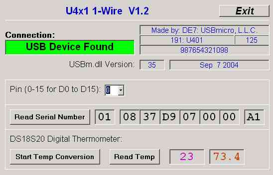
This program initializes the selected port line⁄pin (selected by the pin number drop-down in the example) as a 1-wire bus. It is assumed that for this application there will be only a single 1-wire device located on the bus. The “Read Serial Number” button will read the single 1-wire device on the selected U4x1 pin and retrieve the device serial number for display.
The serial number for any 1-wire device can be retrieved with this application, not just the DS18S20.
Pressing “Read Temp” will read the temperature from a connected DS18S20 device. When the temperature is read, 85 degrees C is returned. This is the default temp that is in the device, if the conversion action has not been performed. By pressing “Start Temp Conversion” then ” Read Temp” the measured temperature will be returned. Please see the data sheets for details.
The first box contains the temperature in degrees Celsius, the second in Fahrenheit (calculated from Celsius).
Screen Shot
Below is the application screen reading the DS18S20 temperature value.
Hardware
The data line (DQ) of the DS18S20 was connected to a pin of the U4x1, the grounds were common, and the VDD pin of the DS18S20 was connected to +5VDC. A 10k ohm pull-up resistor was used on the data line.
DS18S20 Temperature Sensor
App note #9 interfaces a DS18S20 Dallas⁄Maxim temperature sensor to a USBmicro U4x1 device. The U4x1 provides the interfacing signal, ground, and power for the 1-wire temperature sensor.
DS18S20 Pin Assignment
The DS18S20 comes in a small package with three electrical leads. From the graphic below you can see that these leads⁄pins are labeled “GND”, “DQ”, and “VDD”.
The GND connection (DS18S20 pin 1) is ground and provides an electrical reference for the other two signals. Ground on the U401 is pin 9, and ground on the U421 is also pin 9.
“DQ” (DS18S20 pin 2) is the 1-wire data line. Any U4x1 I⁄O line can be configured as a 1-wire bus to communicate with 1-wire devices. Therefore connection from the DQ line should go to the selected U4x1 I⁄O line.
The general configuration for 1-wire devices is to use a bus that has ground and data⁄power lines. The DS18S20, however, draws current during temperature conversion that is higher than can normally be provided on the data⁄power line. Therefore the VDD (DS18S20 pin 3) connection provides power for the DS18S20. This line should be connected to U401 pin 7 or U421 pin 14.

Using Several DS18S20 Temperature Sensors
The U4x1 devices support 1-wire communication with any 1-wire device. When you select an I⁄O port line of the U4x1 to use as the connection to a 1-wire device, you have changed that line from just being a digital I⁄O line to a 1-wire bus. The Reset1Wire command configures the line with a 14 kohm pull-up resistor, and issues a reset pulse on that line. The Reset1Wire command returns (via a pointer – see the command description) an indication of the reception of the device presence pulse.
If you select a particular line to use as the 1-wire bus, you do so with the Reset1Wire command. A Read1Wire command or a Write1Wire command will operate on the line that was last referenced by the Reset1Wire command.
What this means is that you can use all 16 lines on the U4x1 as 16 separate 1-wire busses. Issuing the Reset1Wire command is the way to get the attention of the 1-wire devices on that bus, prior to using the Read1Wire and Write1Wire commands to communicate with the 1-wire device. You can use Reset1Wire to select and communicate with one line of the U4x1, then use it again to communicate with a different line on the U4x1.
You can use all 16 lines on the U4x1 to communicate with 16 1-wire devices, one per line. But you can also have multiple 1-wire devices on each line, and address them individually by using their ROM serial numbers. The 1-wire device documentation contains the details that you need to communicate with 1-wire devices.
The internal 14 kohm pull-up resistor will suffice for a short bus distance, but you should consider supplementing with a 10 kohm resistor external to the U4x1 device. The 10 kohm resistor would be connected between the 1-wire data line and Vcc (+5V).