Purpose
Provide an example to interface the PCF8574 to a U401⁄U421⁄U451. The PCF8574 is an 8-bit I⁄O expander that can connect to the 2-wire bus of the U4x1. Since eight of these devices can be added to the 2-wire bus, the number of inputs or outputs of a single U4x1 can be expanded by eight devices with eight I⁄O lines, or 64 lines total.
Description
The 2-wire capabilities of the U4x1 allow it to interface to the Philips I2CTM devices. The two 2-wire commands can be used together to provide the signaling needed to conform to the signaling needed for the I2C protocol. The 2-wire bus of the U4x1 consists of two open-drain signal lines from port A (or port zero if you want to call it that). Specifically, PA.3 is the 2-wire data line, while PA.2 is the 2-wire clock line.
This application example expands the number of output lines of the U4x1 by eight by using a single PCF8574.
Hardware
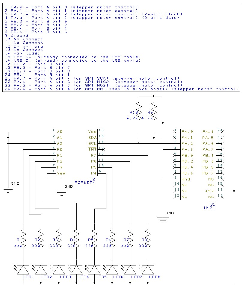
Below is a schematic appropriate for this app note. The circuit uses the two 2-wire lines of the U4x1 (in this case a U421) to control a PCF8574. The PCF8574 will be used as output port expansion in this case. All eight output lines of the PCF8574 directly drive LEDs.
The three address lines of the PCF8574 are tied to ground, making the device address 000 in binary. Since the 2-wire bus is an open-drain bus, two 4.7 kohm resistors pull the lines to 5V. The clock and data lines of the 2-wire bus will either pull the line low or will float open allowing the resistor to pull the line high.
For more information on the PCF8574 and on the other Philips I2CTM devices that the 2-wire interface can drive, please do a big old Google search. There are a LOT of different I2C devices and a lot of information on the web about this type of 2-wire protocol.
Expanded Hardware
Below is a schematic of the same type of system, but it uses three PCF8574 devices. Each of the three devices has a different address, set by the lines A0, A1, and A2.

PCF8574 output using VB6 and USBm.dll
VB Project
This example demonstrates control of a PCF8574 using Visual Basic 6. This VB project builds on the established code base of all of the other example VB projects. The specifics for interfacing to the PCF8574 are described below.
2-wire interface support is in USBm.dll version 65 or newer. You must also use a device with version 3.35 of the device firmware in order to have the 2-wire functionality.
Send a command to the U4x1
| ‘ Write to PCF8574 Private Sub Write8574_Click() ‘ Send init control signal (both lines high) USBm_Wire2Control selectedu4x1, 0 ‘ Send start control signal (drop data line low ) USBm_Wire2Control selectedu4x1, 1 ‘ Send address byte dataarray(0) = 0 dataarray(1) = 1 dataarray(2) = &H70 USBm_Wire2Data selectedu4x1, dataarray(0) ‘ Send data to light up the LEDs dataarray(0) = 0 dataarray(1) = 1 dataarray(2) = ReturnHexByte(Write0Value.Text) USBm_Wire2Data selectedu4x1, dataarray(0) ‘ Send stop control signal (clock high, then data high) USBm_Wire2Control selectedu4x1, 2 State = ReturnHexByte(Write0Value.Text) End Sub |
This code illustrates the steps needed to address and control the PCF8574.
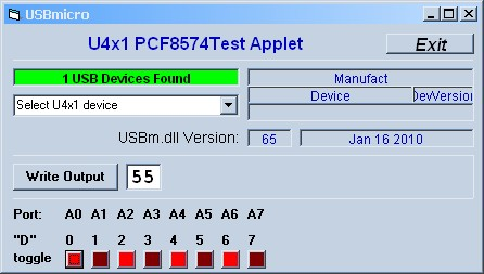
The VB6 code fragment above sends a byte to the PCF8574 to display on the LEDs. Assuming that the hardware is as described in the hardware section of this app note, then PA.3 of the U4x1 is the 2-wire data line, while PA.2 is the 2-wire clock line. These connect to the PCF8574 chip.
The first command in the program listing above distinct to 2-wire control is the init command USBm_Wire2Control selected4x1, 0. The Wire2Control function sends one of several conditions to the two port lines. Three different ones are used here in this code fragment. The first one initialized the port to be open drain and allows the output to be pulled high by external pull-up resistors.
The second Wire2Control command is the command that acts like the “start” condition for I2C. The third Wire2Control command is after the byte writes and makes the two 2-wire lines act like the “stop” condition for I2C.
After the I2C start condition and before the I2C stop condition the code fragment sends out two clocked bytes using two calls to the USBm_Wire2Data command. The first byte correctly addresses the PCF8574 (see the data sheet for details) and the second byte is the pattern to display on the LEDs.